Meshing complex geometry using SOLIDWORKS and STAR-CCM+
Build the CAD model in Solidworks.
1, In excel, transform airfoil data into mm, and add z coordinate;
2, In Solidworks, insert->curve->curve through XYZ points;
3, Open a sketch, convert entities (convert the curves into sketch lines);
4, Close the trailing edge;
5, Features, extrude the airfoil to a wing
6, Open a sketch on the top plane, plot the region to be cut;
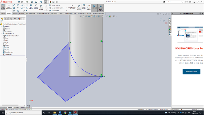
7, Extrude the region to be cut (!!!!!!DO NOT MERGE RESULT)
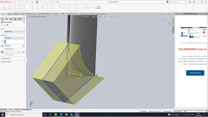
8, insert->Features->Combine subtract the tip region
9, insert->Feature->move/copy rotate the AoA
10, Do a similar thing for the computational domain (!!!DO NOT MERGE when extruding)
11, Save as a step file
Meshing in STAR-CCM+
1, Open star-ccm+
2, import surface mesh
3, Geometry->Parts->Combine2->Surfaces->Face split by patch
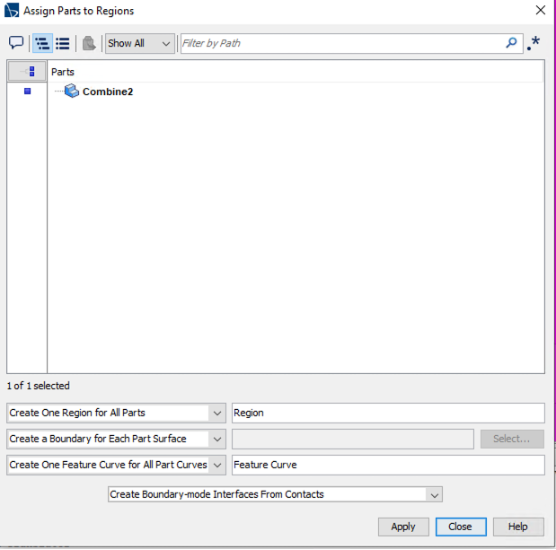
4, Geometry->Parts->Combine2 (right click) Assign Parts to Regions
5, Geometry->Operations->Automatic mesh, Combine2, select surface Remesher, Tetrahedral Mesher, Prism Layer Mesher, set default controls; enable curvature derivation distance. For prism click only generate standard prism; The number of prism layers should be 1, using split mesh in Nekmesh if multilayers are needed.
6, Custom Controls-> surface control, Do surface mesh control
7, Geometry Parts->New shape parts->Cylindric, this part can be used for volumetric mesh control;
8, Click Initialize Meshing, Generate Surface Mesh, Generate Volume Mesh in sequence. Export mesh only, select region and boundaries
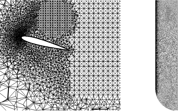
The resulting mesh is