Mesh conversion from Pointwise/Gridgen to Nektar++
In applications Pointwise (or the predecessor Gridgen) is a popular mesh generation software. In this post we go through the procedures to convert the linear mesh generated by Pointwise/Gridgen to arbitrary high order mesh for the solvers in Nektar++.
The mesh conversion takes advantage of the already implemmented Gmsh interface in Nektar++. Assume we have a mesh named mesh.pw, for example, we follow these four steps in Pointwise to set and export the mesh in extension of .msh (the format for Gmsh).
- CAE menu -> Select Solver -> Gmsh
- CAE menu -> Set Boundary Conditions
- CAE menu -> Set Volume Conditions
- File menu -> Export -> CAE
In the above steps, the boundary conditions and volume conditions are set to add tags for boundary element groups and internal element groups. A convenient practice is to define a seperate tag for each of the group so that the settings in these groups can be different.
Now the linear mesh can be directly converted
NekMesh mesh.msh mesh_linear.xmlThe high order mesh is obtained by projecting the linear mesh onto the CAD file in .stp format. This feature is currently available in the branch feature/2D_ProjectCAD of the repository: https://gitlab.nektar.info/ksk119/nektar.git, which will be merged to the master branch soon.
The command for mesh projection is
NekMesh -m projectcad:file=geometry.stp:order=4 mesh.msh mesh_HO.xmlor
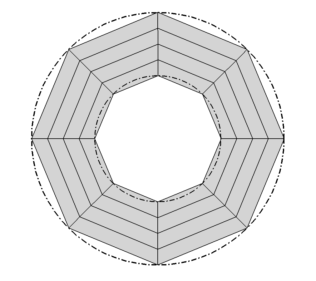
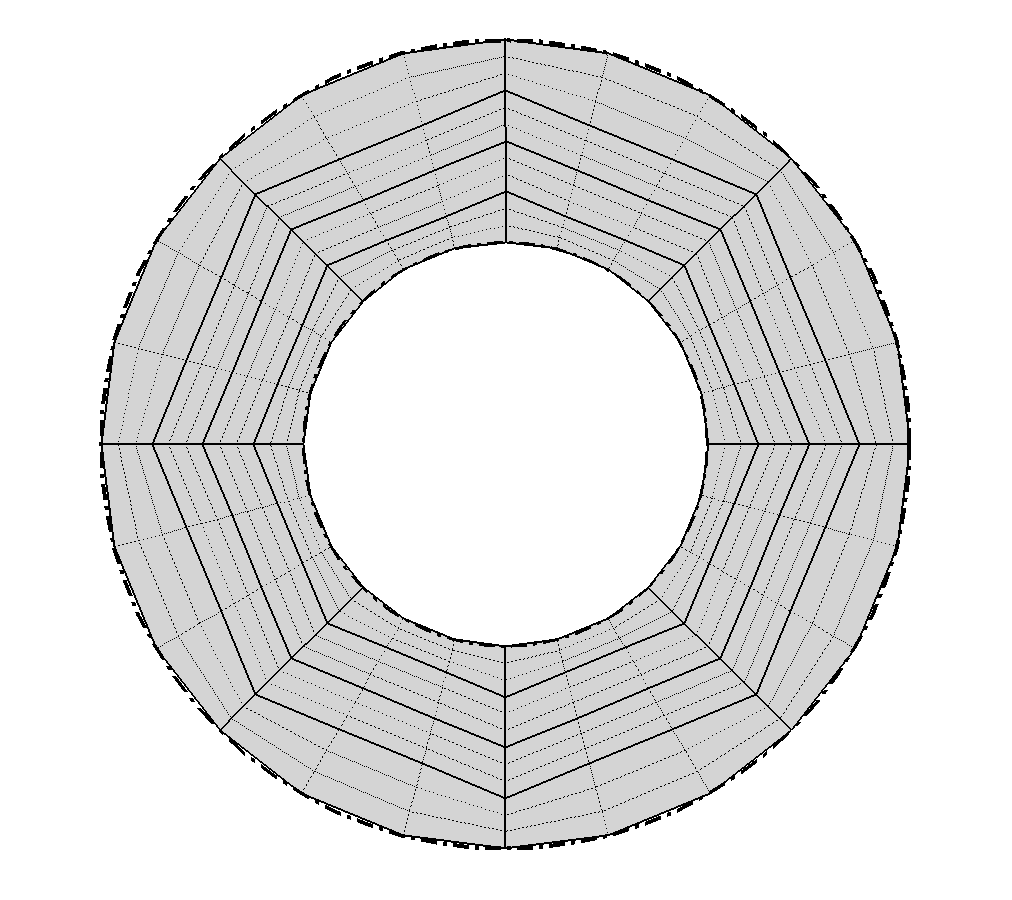
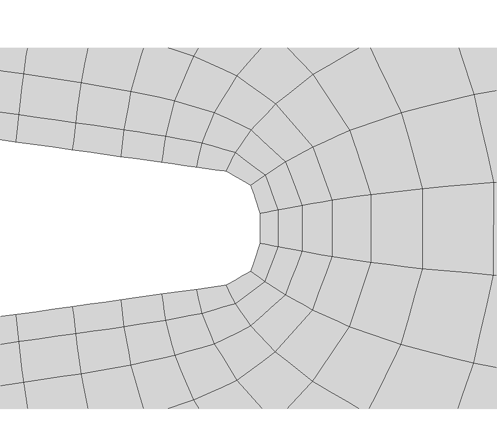
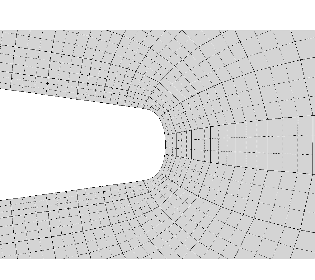
NekMesh -m projectcad:file=geometry.stp:order=4 mesh_linear.xml mesh_HO.xmlTwo examples of high order mesh conversions are given below. The first one uses a simple “thick-ring” geometry and the second example shown the trailing edge region of the mesh projection onto the NACA0012 airfoil. The CAD files (.stp) and mesh files (.xml) are available through this link: https://gitlab.nektar.info/nektar/nektar/uploads/60ea98338227bd53b4bb681e4f567b20/examples_meshProjection2D.zip
To enable the high order mesh to be used by a Nektar++ solver, composite information needs to be provided in the session file. The composite information are at first tagged in Pointwise in the above 2nd and 3rd steps, and can be found in the exported Gmsh file. An example comparing the tags in the mesh.msh and the final mesh_HO.xml is given below
mesh.msh
$PhysicalNames
7
2 1 "structured"
2 2 "unstructured"
1 3 "bottom"
1 4 "inflow"
1 5 "outflow"
1 6 "top"
1 7 "wall"
$EndPhysicalNames
mesh_HO.xml
<COMPOSITE>
  <C ID="1"> Q[0-999] </C>
  <C ID="2"> T[1000-4822] </C>
  <C ID="3"> E[7816,7811,7742,7690,7667,...] </C>
  <C ID="4"> E[7819,7795,7773,7772,7673,...] </C>
  <C ID="5"> E[7820,7794,7655,7714,7804,...] </C>
  <C ID="6"> E[7821,7780,7791,7712,7761,...] </C>
  <C ID="7"> E[0,4,7,10,13,93,96,99,102,...] </C>
</COMPOSITE>
<DOMAIN> C[1-2] </DOMAIN>
where in the left column the “structured” represents the quadrilateral boundary layer elements with composite ID=1 in the right column while the “unstructured” represents the triangular outer elements with composite ID=2. The other tags (composite IDs) will be used for the boundary condition settings.