Compressible flow
Nektar++ includes a solver for simulating the dynamics of compressible inviscid/viscous flow on unstructured two-dimensional and three-dimensional meshes. Specifically, the solver solves two system of equations:
- Euler equations;
- Navier-Stokes equations.
The systems are provided with a comprehensive set of boundary conditions (1) for specifying inflow/outflow variables as well as wall conditions. In both the systems appropriate techniques for shock-capturing when dealing with transonic flows are included.
At the moment, the equations are solved with a Discontinuous Galerkin (2) method in two-dimensional grids (triangles, quadrilaterals) and three-dimensional grids (hexahedra, tetrahedra, prisms, pyramids). Alternatively the two-dimensional cases on quadrilateral meshes can be solved with a Flux Reconstruction approach (3).
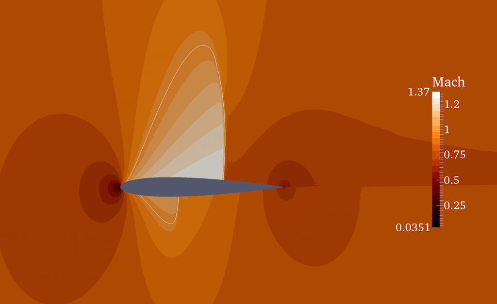
In the following we show some external aerodynamics problems solved using the Nektar++ compressible flow solver. The first picture shows an inviscid Euler simulation of flow over a NACA0012 aerofoil at Ma = 0.8 and an angle of attack of 2°. It is possible to appreciate how both the shocks on the upper surface and the lower surface are well captured.
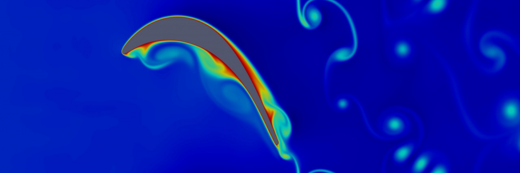
The image below shows temperature of flow passing over a T106C low-pressure turbine blade. The picture was obtained solving the compressible Navier-Stokes equations at Re = 80,000 with an isothermal wall and periodic boundary conditions the third direction.
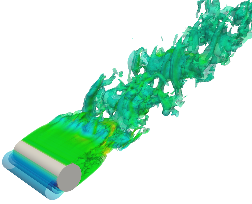
The image below shows the flow over a cylinder at Ma= 0.2 and Re = 3,900. Specifically, the picture depicts the isocontours of Q-criterior coloured and shows the turbulent wake behind the cylinder.
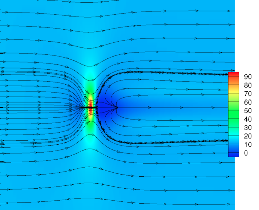
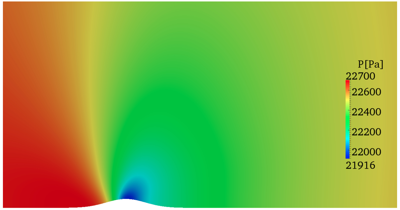
The compressible solver has been used as DNS tool within the LFC-UK group at Imperial College whose final aim is the development of an underpinning technology for laminar flow control. From this perspective several studies of boundary-layers over roughness elements like those over aircraft wings have been performed (4). The following picture shows the pressure of a transonic boundary layer flow at Ma = 0.87 encountering a two-dimensional hump.
In the following image the limit streamlines of wall shear stress of equivalent study of a boundary-layer flow over a three-dimensional are depicted. It is possible to note the separation point from where all the streamline diverge after the hump (red area). The recirculation region (blue area) behind the hump extends from the separation to the reattachment point where the limit streamlines are directed outward way from the node.